Step 5 Google Drive Continued
Well it took me a while but I did find a way to install grive and have it work. Thanks to Nathan
HERE Below is the how to just commands no explanation why. Using a ssh program like putty will make your life much easier for this due to the steps after all the code runs. There are a few differences from his. First I added the wget to download the patch. Second I had to change the patch command because his downloadable files name changed at some point. At the end it will give you a website to go to to get authorization from google. Copy the website, go to it, accept the conditions (if you don't want grive to have access to your account then I suggest making another google account). Copy the access code to the terminal and hit enter. If everything goes according to plan, it will start synchronizing your google drive to the folder GoogleDrive (remember capitalization really matters in Linux) While you wait go get a coffee or bowl of ice cream or something, it may take a while. When it is all done it will say finished and you will have a command prompt again.
{{
wget
http://www.nburles.co.uk/sites/default/files/attachments/State.cc_.patch
sudo apt-get install git cmake build-essential
libgcrypt11-dev libjson0-dev libcurl4-openssl-dev libexpat1-dev libboost-dev
libboost-filesystem-dev libboost-program-options-dev libboost-test-dev
binutils-dev libyajl-dev qt4-dev-tools patch
cd ~
git clone git://github.com/Grive/grive.git
patch ~/grive/libgrive/src/drive/State.cc -i
~/State.cc_.patch
cd grive
cmake .
make
mkdir ~/GoogleDrive
cp ~/grive/grive/grive ~/GoogleDrive
cd ~/GoogleDrive
./grive -a
}
Now that everything is copied you can type {{ls}} to see all of the files are copied. For my purposes if I am missing a picture or 2 its not the end of the world, if you are using this for a backup of files you may want to check to make sure everything copied. WARNING, you have to tell grive to check for files changes instead of it checking all by itself continuously. For a picture frame this isn't really an issue in my book. We will go over scheduling events later.
Step 6 Frame Buffer
Now I choose to use fbi, if I could find a command line based image viewer that had transitions I would but I havnt found that yet so I am sticking with fbi for now. The install for this is super simple
{{
sudo apt-get update
sudo apt-get install fbi
}}
Thats it. I wish grive could be installed that way. Again the above and below comes from someone else work, I just brought it all together. His page can see his page
HERE. Now he creates a folder to store his pictures in because he copies his pictures to the sd card directly instead of having it done automatically. Now he suggests creating a user that logs in when the device is powered and I see no reason not to so here is the code to do that. {{
sudo adduser slideshow --ingroup video}}. This is going to ask you a bunch of questions. I hit
enter 6 times then
n then
enter, then
enter 5 more times, then
y then
enter. We now have a blank user created without a password named slideshow. Next we need to make that user log in at boot which is a little fun. First open inittab file by {{
sudo nano /etc/inittab}}. Now we need to find a specific line {{
1:2345:respawn:/sbin/getty --noclear 38400 tty1}}. When you find it put a {{#}} in front of it to comment it out. Add a blank line right after it and insert the following {{
1:2345:respawn:/bin/login -f slideshow tty1 </dev/tty1 >/dev/tty1 2>&1}} Now exit with {{
^x}} then
y then
enter. Now at boot the user slideshow will log in. If you did not want to create a new user you should be able to replace slideshow in the previous orange block with pi, now I am not sure if it will log in since pi has a password and slideshow does not.
So far we have gotten raspberry pi to boot, installed grieve and fbi. We can not get pictures off of google drive, and we can show them using fbi. Now its time to deal with the weather display.
Step 7 Weather display
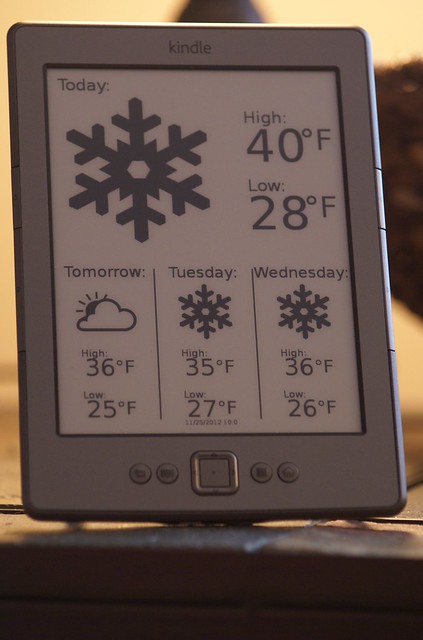
The weather display was something that I added to what other people have already done. This was something that I thought would be a good idea, something that would take this project to the next level. My original plan was to use a web browser of some sort but I couldn't figure out how to get the web browser to load from the terminal so I changed tactics. I got the idea from the people who used an old kindle as a wall mounted weather display. What that group did was they used a webserver to download the information off the internet, and then convert it to an image than the kindle could the display. Well I thought, hey my picture frame is already setup to display images I just have to download the information. So I got the files I needed for the kindle project and made them fit my own needs. The first of which was adding information fields to the final output. See the kindle weather display only shows 4 days of weather total. Since I had a much bigger screen I figured I should show more information. I show 6 days of information, plus the day and current date.
There are 2 programs that we need for this to work. 1. is python which comes preinstalled. 2 is rsvg-convert. Now googling that may cause some problems trying to find the installer. that is because rsvg is part of librsvg2-bin so that is what we need to install{{
sudo apt-get install librsvg2-bin}}. The reason we need this is because the python file creates a svg file and fbi will not display that. This outputs a png file which we can. Later I will come back to actually getting the weather information. You can download the weather files
here.
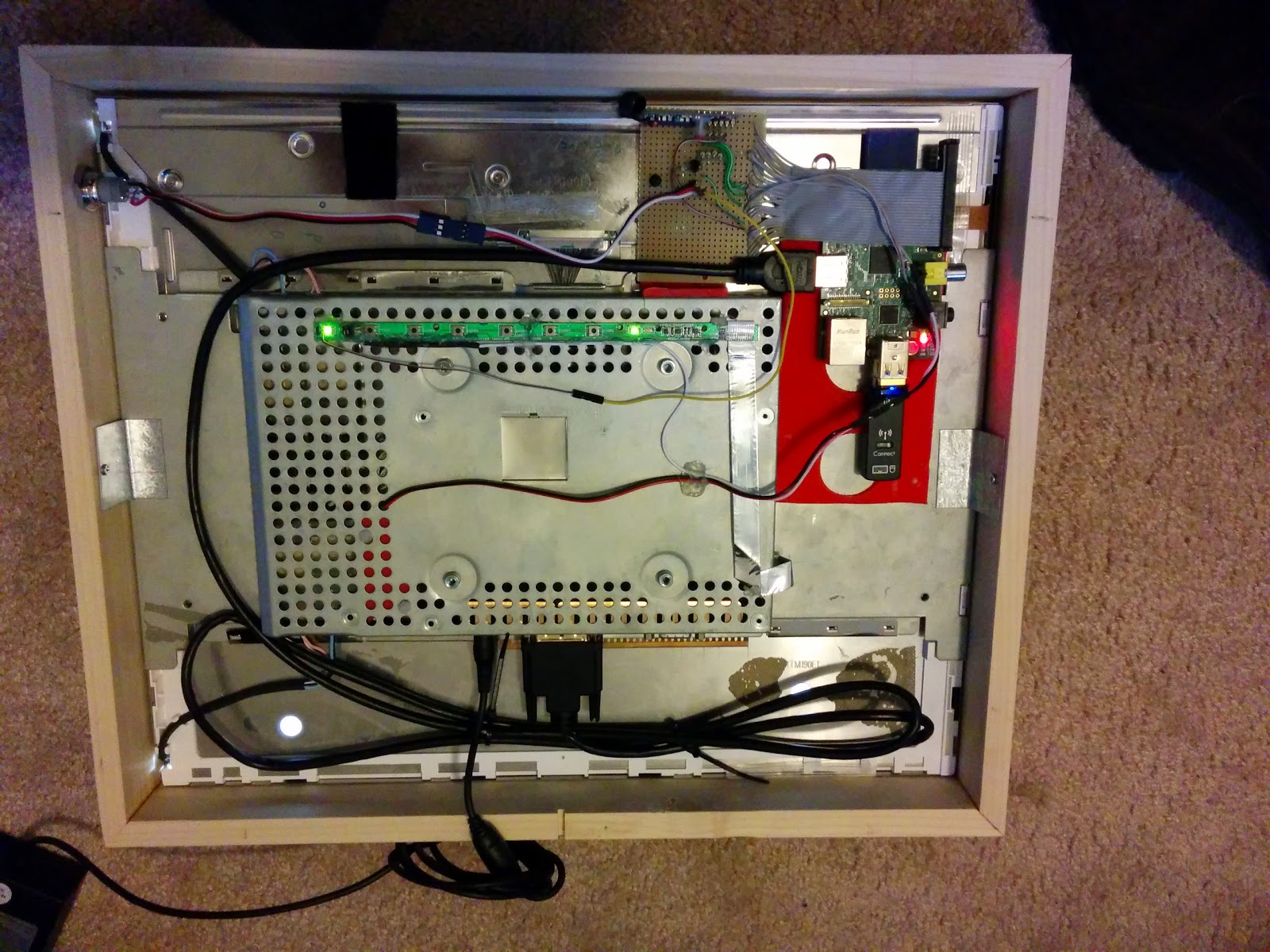
Step 8 IO
Instead of adding buttons to the picture frame itself I decided it would be nice to have a wireless remote so that you could control the frame from your desk. Again there are multiple ways to access the gpio on the pi. I went with the way the guy did it from
HERE. Same guide on how to setup fbi. Everytime the pi starts we are going to have to run a script to get the gpio setup correctly. I need 5 pins. 4 for input from the remote, and 1 output to turn the monitor on and off. Setup is easy enough, for each pin you need the following in a sh file. (you can download all of my required files
here) Mine is called gpiosetup.sh. Every where there is an 18 make that what ever pin that you are currently using. I used 17,18,22,27 for inputs and 24 for an output. Now your probably curious why I choose those pins for those purposes. I choose those numbers so they would right by each other on the actual pin header.
Here is a pin out I found on google.
{{
# export GPIO pin 18 and set to input
echo "18" > /sys/class/gpio/export
echo "in" > /sys/class/gpio/gpio18/direction
}}
{{
# export GPIO pin 18 and set to output
echo "18" > /sys/class/gpio/export
echo "out" > /sys/class/gpio/gpio18/direction
}}
No we need to create a script to check if any of the inputs are being activated.If you are downloading my scripts I called it IOcheck.sh. Since we want this to run continuosly we need to have a while loop. Button D on my remote is wired to gpio17. Since I had to do a voltage diver circuit to get safe voltages for pi I am not worried about setting up a pull up or down resistor in the earlier code. This also means I have a pull down physically installed.
"$( cat /sys/class/gpio/gpio17/value)" gets the status of the button presses. I have found that I need to hold the button down for a little bit not just a quick press and release. In the if statement below I turn an output on for a half second, then off and wait a second. That output is wired to a transistor setup to act as a button that is connected to the monitor power button. This way I can physically turn the monitor on and off. Some people have chosen to just send a black screen or disable video output so the monitor goes to sleep but I would rather actually turn the monitor off. I may add in that if this button is help for an extended period of time it tells the pi to shut down, but I will save that for later. Copy everything between do and done below and paste it for each input you have.
{
while [ true ]
do
#Button D
if [ "$( cat /sys/class/gpio/gpio17/value)" == '1' ]
then
sudo echo 1 > /sys/class/gpio/gpio23/value
sleep .5
sudo echo 0 > /sys/class/gpio/gpio23/value
sleep 1
fi
done
}}


