A while ago this blog (
http://thegreatgeekery.blogspot.de/2016/02/ecoplug-wifi-switch-hacking.html) was featured on hackaday. I went on the search to buy one to play with. I found them at
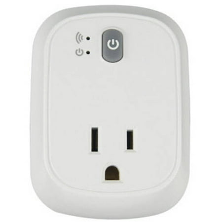
walmart for a decent price. For those who didn't read the blog at that I mentioned.
These outlets have an ESP8266 in them which make them great for hacking purposes. The one I got from Walmart actually included the current monitoring circuity if you want to implement power consumption. If you ware going to take the work choice outlet apart be careful when putting it back together. I broke the wires that connect the low voltage board to the high voltage board off of both boards. Just something to be aware of. I also added a programming header to the side so I do not need to take it apart anymore to update the code. I plan on doing over the air updates but I haven't figured that part out yet.
While I did just convert that to my openhab setup, I have also been working on building my own from scratch. Which in the long run is very easy, I only used the following parts
- ESP8266 development board
- small bread board
- 2 channel relay control board
- 5v power supply
- 2 buttons
- outlet
- box
- 2 ws2812 leds (optional)
Since I was trying to do this as inexpensively as I could I bought all of the electronics from china. All of the electronics where under $10. I bought the outlet, double gang box and face plate from my local hardware store for under $5. The LEDs are behind the buttons which give them a nice little glow. I am planning on reprinting the orange one soon so it fills the holes a little better and glows more evenly.
The code for both of these projects were almost the same. I had to change the I/O some and the device ID but otherwise the code was the exact same. I did not use the energy monitoring from the commercially available product. One problem i do have currently is when i first plug in the double outlet the one outlet gets turned on for a little bit of time and then it turns right off again. It looks like the pin gets pulled low while the ESP is booting up. I need to go take a look at this and change the output pins so that this problem goes away
Above is the programming board that I made. The header on the left goes to the new header on the side of the workchoice. It has the following pin out not in that order.
- 3.3 v
- gnd
- reset
- gpio0
- tx
- rx
I also have a header on there if I want to program an esp 1. The right header is for my ftdi cable. Unluckily it has a 5 v power line even though it is 3.3v logic level so I had to put a voltage regulator on there. Another capacitor wouldn't hurt to help smooth out the output since it is an lm3171 but it is working fine for now. . Next is to build a nice looking outlet from scratch, then on to a light switch. But before I get to that I need to find a nice 120 vac to 3.3 vdc circuit as well as prototype with triacs instead. I also want to use capacitive touch instead of actual buttons since I can find a good button for my light switch.


No comments:
Post a Comment