Friday, December 26, 2014

Laser Cutter Fun 2

Owls
Student Graduation Cap Topper
Millersville University
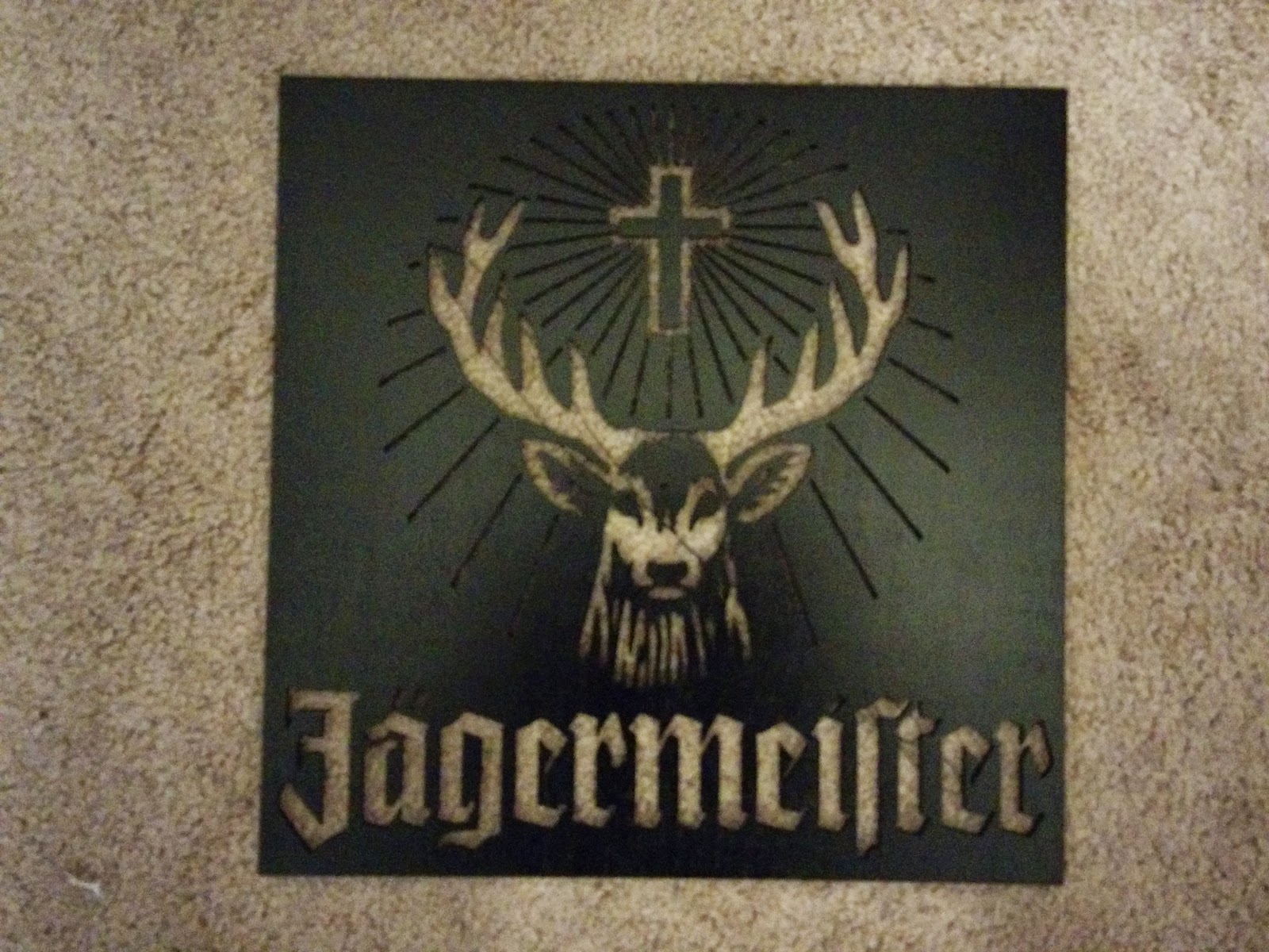
Jägermeister

Olaf from Frozen

Rutgers Scarlet Knight


Monday, December 8, 2014

Raspberry Pi Picture Frame Post 14 Final


At this point I believe the project is complete minus one part. Finishing the frame but that is going to wait until the final user chooses how they want it finished. Major software changes since last time where
  • When pictures are re-sized they are moved to a new folder then the originals get deleted. 
  • Frame can now be programmed to turn the screen on or off at given times because it knows if the frame is on or not. 
  • Divided some of the scripts up into separate scripts for easier troubleshooting 
  • Made the button to turn off the screen have 3 functions (no limit to number of functions)
    • 1 turn screen off. (quick press)
    • 2 preform a sync with google (press until blue led turn off about 3 seconds)
    • 3 power off the pi (press until pi starts shutting down. about 5 seconds)
Overall I am really happy with how the project came out. All of the individual pieces have come together to make a really neat picture frame that looks exceptionally nice. Here is a copy of all of my scripts used and Here is the stuff for the weather,If you have any questions all you have to do is ask.

       
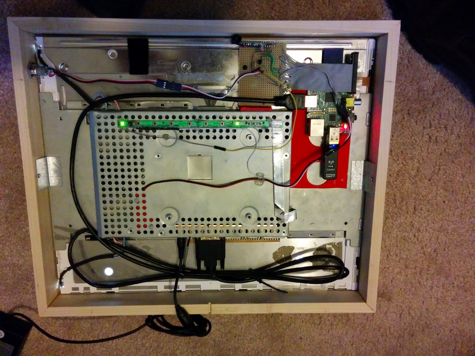
Mount holding monitor in framePower button with Blue LED
Back View

Thursday, December 4, 2014

Raspberry Pi Picture Frame Post 13 Update

The picture frame has come a long way since the last post. I now have the wooden frame for it built and almost done but we will come back to that in a minute. Since the last update I have completely remade some of the electronics. The only reason I did this is because I fried 2 different wireless receivers for my button inputs and since I wanted to add a few more items I decided to basically start from scratch. Beyond the remote control for input I added the following items


  • On board power switch that turns the monitor on and off
  • The switch has a LED in it which will tell you the status of the screen
  • Input for monitoring status of screen

Above you can see my old setup (on the bottom) and my new setup (on the top). Yes it is probably 3-4 times bigger but you never know what you may want to add to the project down the line so I left it big. It helps that I have excess space so I can easily leave it big. On my old setup I had the resistor divider n the back of the wireless receiver. This time I have it on the perf board. To add the power button I had a few options. 
  1. Wire the button in parallel with the original monitor button
  2. Wire the button in parallel with the remote button that tells the pi to turn the screen on or off
  3. Wire the button to a new input
I liked the hardware approach better than the software approach so that took off one option. To keep the number of wires coming off my new board to the bare minimum I decided to wire the switch in parallel with the wireless receiver. The power button I used is from adafruit and can be found here

Instead of having 4 wires coming back from the switch (LED +, LED -, Switch Common, Switch Normally Open) I only have 3 (5v, Switch Nomally Open, LED -) I have done me best to make each different part removable in case something breaks it should be pretty easy to replace. Since everyone likes schematics you can see mine below. 

You will notice that I also have a transistor setup to switch the LED on instead of relying on the PI to supply enough current. I also wanted it to run off 5 volts instead of the 3.3 the pi will put out. There is also a transistor right by the monitor button. At this point I have not done any additional coding but all of the hardware is now done.

Now on to the actual wooden Frame. Due to the thickness of the monitor I new the frame was going to be thick and it doesn't bother me one bit.


I got the wood from my local Lowes. Each side is made up of a 1/2 x 3 and 1/4 x 1.5 glued together.


I glued them together mitered the corners and glued it all together to make a nice frame. Then I cut it down to a little over the thickness of the frame so it wouldn't be to excessively thick. I still need to add a hole for the button and make a notch bottom center for the power cord to come out in case it gets hung on a wall. 


Sunday, October 26, 2014

Laser Cutter Fun

A few weeks ago I was asked to help with a presentation on 3D printing. I was asked if there was anything we could print as examples that we could give out to each participant. We wanted something related to ISU but I couldn't find anything so I decided to make a sycamore leaf with ISU in it. http://www.thingiverse.com/thing:494399 Design was it was a very simple process. I imported a sycamore leaf into inventor and then just traced it. Added some text and a hole at the top and it was done. Now when talking to people who have no idea what 3D printing is they can have a hard time understanding how the machine works and all of the layers. So I decided I should laser cut out a few layers so I could show them layer by layer how it works.
After cutting these things out I realized that they would make nice decorations so I cut out a bunch of them out and started giving them to people. Personally I like the one in the middle the best. Not only does the middle one look nice, so does the pieces that cut out and glued to a backer board.
After making a bunch of these I started thinking about what other things I could laser cut out. Came up with a fee ideas for presents so this will be updated after they have been distributed.

Sunday, August 31, 2014

Rigidbot Modifications

After having my 3D printer for a while and doing long prints I got tired of having the printer running in my room. Sure it was nice when it was time to check on my prints, but sleeping with the thing running was not ideal. So the first thing I did was add a raspberry pi running OctoPrint. If you have not heard of OctoPrint it adds a web interface to control your printer. It even allows you to add a webcam so you can easily do time lapses of your prints or see how the print is coming from anywhere with internet. (That is on my list to add) This interface allowed me to move my printer to another room in my house.

Now That I add the raspberry pi I now have to plug my printer into the power brick, plug the raspberry pi into the printer, and the raspberry pi into the wall for power. To me that was a little ridiculous so I decided I wanted to mount everything to the printer so it was one plug and done. This was going to be a project for farther down the road except one day the printer would not start. It turned out that the plug from the power brick to the printer was not the best connection in the world. I was not a fan of that plug to begin with but figured don't fix what ain't broken. Well once the plug stopped working I figured it was time to replace it and mount everything to the printer. I also wanted to make a stand so the printer would be at table height. That part is not done yet but the important part is the printer is printing again.

Now I decided that the raspberry pi, power supply and control board would all mount to the dame tray. That way if I needed to work on something I could take it all out in one piece. I measured the distance between the bars and how long the power supply was and made the tray below.
Due to my need for precision after taking a metal working class at my undergrad (this has gotten me into trouble before) The metal tray was a hair tight. Should have made it a 1/16th smaller but it still fits and that is what is important in my book.
Now I had a general idea of how the electronics where going to get layed out before I built the tray but here was the plan once the tray was made.
Now it was time to start attaching things to the tray. I decided to use the orignal box for the controller so that it would be protected and I would know what plug was what. I needed to insulate the raspberry pi from the tray as well as the dc-dc voltage converted (this way I would not need to have a second plug for the raspberry pi). The power supply would be held in with a metal strap. 
I thought about 3D printing a raspberry pi case and something for the power converter but whey spend the hours printing that when in under 10 minutes I can draw up a 2D spacer and laser cut it out. Now in the above picture you can see the electrical work already done. Originally I was going to have to have 2 sets of wires connecting the power supply to the control board. You can see the second plug in this picture. After I had wired the wires to the power supply I thought about it and did a quick Google and determined that the 10 gauge wire I was using and the power connectors would be able to hand the current with just one plug so I only soldered 1 to the control board. I will remove the other plug later when I move the 120 vac plug from the back of the power supply to the printer itself. Now we all know how big of a pain it is to wire things together when space is tight. So to make my life easier my tray just pivots on 2 of the screws holding it in so it is easy to plug everything in and work on anything if needed. 

After I got everything all wired in all I had to do was rotate the panel back into the bottom of the printer and put the other 2 screws in. 

That's it for stage 1. It will probably be a bit before stage 2. Which will include moving the 120 vac plug, painting everything, replacing the USB cord with a 6 inch one so I don't have a cable coiled, and finishing the stand. Currently it is a little wobbly.


Wednesday, August 20, 2014

Raspberry Pi Picture Frame Post 12 Image Resizing

As I said in my last update I said that I wanted to resize images to save space on the pi. To do this I am going to use imagemagick. You can install it using the code below.
sudo apt-get update
sudo apt-get install imagemagick
If I remember correctly I mentioned earlier that capitalization is extremely important with Linux. This includes file extensions. If you use my scripts the slide show will only show .JPG files not .jpg. So to fix that we need to make sure all of the pictures have .JPG as there extension. This is done with one simple line of code.
rename 's/\.jpg$/\.JPG/' *.jpg
Now if you want an explanation of what everything in the code means go here. I tried to explain it but in the end that's where I got the help from and that website does a much better job. So I gave up on explaining. Now all of our files have the same .JPG extension. Next we will resize the pictures. If you want to just do one the command is convert input.JPG-resize 1280x1024 output.JPG. Now in that case we can change the file name output and the extension. However when we do a batch process it does not work nicely. Below is the batch convert code. 
for file in *.JPG; do convert $file -resize 1280x1024\> $file; done;
Now lets break that down. for file in *.JPG; What this means is for each file found with the .JPG extension we will do the following. The $file allows the command to use the file name from the for section. The done at the end says that we are done looping commands, go to next file. Just search batch convert imagemagick if you want more information. The \> says to only re size bigger images. This way we don't reprocess each image every night. Now I am going to add this to the grive.sh script. What I want it to do is check for changes (aka new pictures) and download if there are, then convert the files, then sync the new files to the web. 

Monday, August 18, 2014

Raspberry Pi Picture Frame Post 11 Progress Update

Now that I am finally back in Indiana I have got the picture frame setup and it is working like a charm. That is once I got it connected to the internet again. Today I gave out the information so that my siblings could start uploading pictures to the frame so that I can give it a good test. just over 4 months till Christmas when I need this thing working perfectly.

Things I have changed since my last post.

  • Added picture re sizing. I was putting the files as the came off my camera directly onto the picture frame. These files were about 3mb. I setup the picture frame to resize the images down to the make resolution of the screen. That way the files are smaller and more will fit on the memory card. They are about 1/5th the size they were originally. (will write up how I did this later once I figure out how I did it.
  • Moved picture locations. Instead of having the pictures in the main google drive folder. I moved them to a folder called pictures. This allowed me to share that folder with edit capabilities with other family members so that they to could add pictures without me having to give them my username and password. 
Things to be done
  • Build the nice wooden frame. Luckily I have access to a nice wood shop out here which will make my life much easier.
  • Add a external light so you can tell when the screen power is on and off. Now you may be wondering why I want to do that since the screen will be showing pictures when it is on. Simple. When you use the remote to turn the screen on you don't know if its powering on unless you wait since there is about a 5 second delay for power on
  • Add a gpio input for screen power. This way we can schedule events to turn the screen on and off. Without this if the screen is already off and the off event comes it will just turn the on which is the opposite of what we want. 
  • Change weather screen 2. I said this in a previous post but I plan on changing the second weather screen to show the weather in 4 different locations.