Wednesday, June 10, 2015

Home Automation Part 3 rpi static ip, On LED, and Arduino Code

Static IP

The worst thing that can happen to you is your ip address on your server changing every once in a while. When that happens you either need to change it back or change all of your devices that talk to it. So you will want to nip that in the but early and set a static ip address for your server that is never going to change. To do that you need to modify /etc/network/interfaces
sudo nano /etc/network/interfaces
In that file you will see either iface eth0 inet dhcp or iface eth0 inet manual. we need to change that to iface eth0 inet static
Now that we are not getting information from the router we need to set that information our selves. Copy and paste below into the file. X should be the "class" of your router. Class is the best name I got. Most routers use either 0 or 1. A should be the address you want your server to be. It has to be between 1 and 254 and cant be your gateway. Pick your poison. B is where you can access the router config. This is usually either 1 or 254
address 192.168.X.A
netmask 255.255.255.0
network 192.168.X.0
broadcast 192.168.X.255
gateway 192.168.X.B
While we at it we might as well change the hostname of the pi. it standard name is I believe raspberrypi. There are 2 files we need to modify. /etc/hosts and /etc/hostname
sudo nano /etc/hosts
You want to change the last line which starts with 127.0.1.1 to whatever you want your hostname to be.
sudo nano /etc/hostname 
Change this file to the same as in the previous file.Then run the following commands to update the hostname and reboot the pi.
sudo /etc/init.d/hostname.sh
sudo reboot
Now make sure when you ssh back into the pi you use your new ip address

On LED

Now I get tired of having to guess when I can ssh back into my pi everytime I reboot it. So I created a small script that turns an LED on when I can ssh back in. 
# export GPIO pin 4 and set to output
echo "4" > /sys/class/gpio/export
echo "out" > /sys/class/gpio/gpio4/direction
echo 1 > /sys/class/gpio/gpio4/value

Basically you set a gpio to output, and set the pin to on or 1. In the above I use pin 4 since it had a ground right next to it. Then wire an LED to it with the proper polarity and run the script at start. To make ir run at start add sudo sh /location/of/script/name.sh  before exit 0
sudo nano /etc/rc.local

Now every time the pi restarts the LED will turn on when you can access it again. It also will turn off when the pi is completely shutdown letting you know when you can unplug it safely.  

Arduino Code

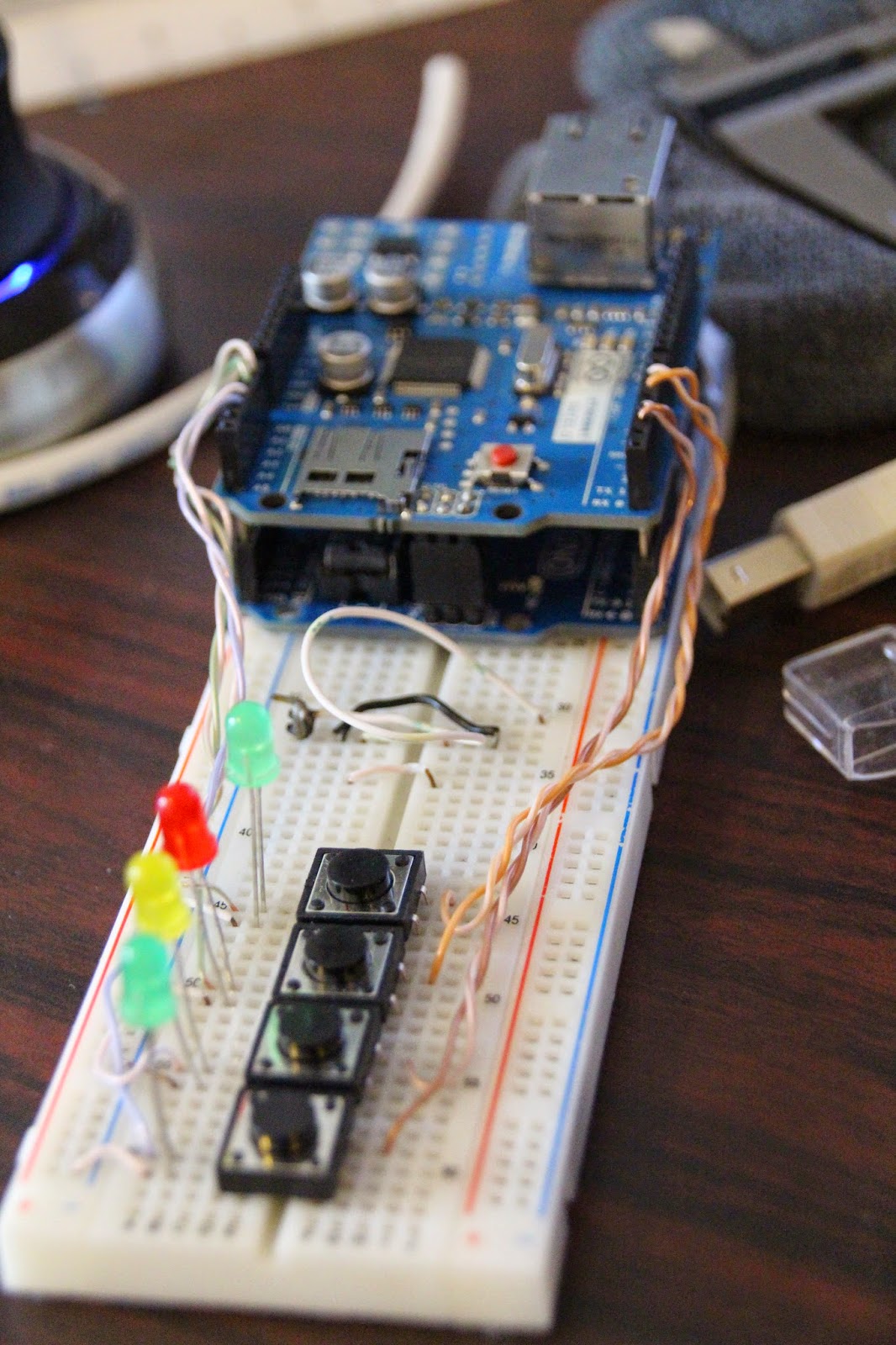
For testing purposes I have been using an arduino UNO with an Ethernet shield. The code so far has not been test on anything but that. What I have done with the code is everything that needs to be changed is changed in the variables at the top of the code. There are only 3 things that need to be changed. 1st is the devID. This is the ip address of the device as well as what topics it subscribes and publishes too. Second is IOcount. This is the number of buttons and outputs you have. For simplicity I have one button for each output. In the code the buttons will turn the output on when they have internet access or don't. The last item that needs to be changed is the mac address. I am planning on making that dependent on the devID as well that way it is one less item that needs to be changed. For outputs I am using the analog pins A0-5 and for inputs I am using 2,3,5-8. I am sure that my code could be improved upon and if you do let me know but here it is as of now. you will need to install the pubsubclient library and make sure it is installed properly, I had to move folders around due to the version number. Arduino Code Download. Now it is time to get the ESP8266-07 working.

Tuesday, June 2, 2015

Home Automation Post 2 openhab and mosquitto install

I have been messing around with openhab for a little bit now and I could not get mqtt to work for the life of me. So what do you do, start back at the beginning. Since this is the beginning of the project the only thing I lost was the rasbian image (which is just a few clicks and some time away from being installed) mosquitto install, and openhab install. This time I followed different installers for openhab and mosquitto and would you know. Now mqtt works without an issue.

OPENHAB
To install openhab I followed the directions on https://github.com/openhab/openhab/wiki/Linux---OS-X. Make sure that if you want to use mqtt you install that addon using _________

echo "deb http://dl.bintray.com/openhab/apt-repo stable main" | sudo tee /etc/apt/sources.list.d/openhab.list #part of previous line
sudo apt-get update
sudo apt-get install openhab-runtime
#will have to type a small y in to install packages
sudo apt-get install openhab-addon-binding-mqtt
#will have to type a small y in to install package
sudo update-rc.d openhab defaults # makes openhab run at boot

MOSQUITTO
mosquitto was a bit easier to install

sudo apt-get install mosquitto mosquitto-clients python-mosquitto


Wednesday, May 20, 2015

Raspberry Pi Picture Frame Post After finished

A useful tool for configuring wifi from the command line is wicd-curses. It gives you an almost gui interface in the command line. Great for configuring wifi over ssh. To insall
sudo apt-get update
sudo apt-get install wicd-curses

Monday, May 4, 2015

Home Automation Post 1

Home Automation has been a dream of mine for a while now but not having a good location to test it in has put the project on hold. The other issue was a cheap wireless connection between devices but with the esp8266 that has now partially been solved. I haven't received my modules yet and I wanted to start working on this so I am starting with a arduino uno with an Ethernet shield. I am looking at using MQTT as my way of sending information back and fourth between the esps and a raspberry pi as my server for both the website and all of the MQTT transactions. I have installed mosquito on the rpi as a broker. Time for the fun to begin.
 

Friday, December 26, 2014

Laser Cutter Fun 2

Owls
Student Graduation Cap Topper
Millersville University
Jägermeister

Olaf from Frozen

Rutgers Scarlet Knight


Monday, December 8, 2014

Raspberry Pi Picture Frame Post 14 Final


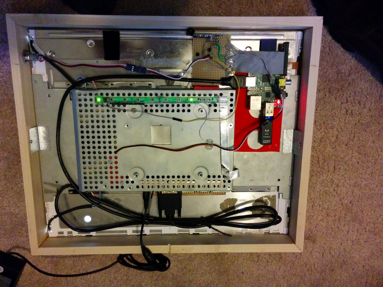
At this point I believe the project is complete minus one part. Finishing the frame but that is going to wait until the final user chooses how they want it finished. Major software changes since last time where
  • When pictures are re-sized they are moved to a new folder then the originals get deleted. 
  • Frame can now be programmed to turn the screen on or off at given times because it knows if the frame is on or not. 
  • Divided some of the scripts up into separate scripts for easier troubleshooting 
  • Made the button to turn off the screen have 3 functions (no limit to number of functions)
    • 1 turn screen off. (quick press)
    • 2 preform a sync with google (press until blue led turn off about 3 seconds)
    • 3 power off the pi (press until pi starts shutting down. about 5 seconds)
Overall I am really happy with how the project came out. All of the individual pieces have come together to make a really neat picture frame that looks exceptionally nice. Here is a copy of all of my scripts used and Here is the stuff for the weather,If you have any questions all you have to do is ask.

       
Mount holding monitor in framePower button with Blue LED
Back View

Thursday, December 4, 2014

Raspberry Pi Picture Frame Post 13 Update

The picture frame has come a long way since the last post. I now have the wooden frame for it built and almost done but we will come back to that in a minute. Since the last update I have completely remade some of the electronics. The only reason I did this is because I fried 2 different wireless receivers for my button inputs and since I wanted to add a few more items I decided to basically start from scratch. Beyond the remote control for input I added the following items


  • On board power switch that turns the monitor on and off
  • The switch has a LED in it which will tell you the status of the screen
  • Input for monitoring status of screen

Above you can see my old setup (on the bottom) and my new setup (on the top). Yes it is probably 3-4 times bigger but you never know what you may want to add to the project down the line so I left it big. It helps that I have excess space so I can easily leave it big. On my old setup I had the resistor divider n the back of the wireless receiver. This time I have it on the perf board. To add the power button I had a few options. 
  1. Wire the button in parallel with the original monitor button
  2. Wire the button in parallel with the remote button that tells the pi to turn the screen on or off
  3. Wire the button to a new input
I liked the hardware approach better than the software approach so that took off one option. To keep the number of wires coming off my new board to the bare minimum I decided to wire the switch in parallel with the wireless receiver. The power button I used is from adafruit and can be found here

Instead of having 4 wires coming back from the switch (LED +, LED -, Switch Common, Switch Normally Open) I only have 3 (5v, Switch Nomally Open, LED -) I have done me best to make each different part removable in case something breaks it should be pretty easy to replace. Since everyone likes schematics you can see mine below. 

You will notice that I also have a transistor setup to switch the LED on instead of relying on the PI to supply enough current. I also wanted it to run off 5 volts instead of the 3.3 the pi will put out. There is also a transistor right by the monitor button. At this point I have not done any additional coding but all of the hardware is now done.

Now on to the actual wooden Frame. Due to the thickness of the monitor I new the frame was going to be thick and it doesn't bother me one bit.


I got the wood from my local Lowes. Each side is made up of a 1/2 x 3 and 1/4 x 1.5 glued together.


I glued them together mitered the corners and glued it all together to make a nice frame. Then I cut it down to a little over the thickness of the frame so it wouldn't be to excessively thick. I still need to add a hole for the button and make a notch bottom center for the power cord to come out in case it gets hung on a wall.