Sunday, October 1, 2017

Raspberry Pi Picture Frame Post 16 update 10/1/17

Building another picture frame so I am going to attempt to condense everything to one page

Google drive sync - https://github.com/prasmussen/gdrive 

#download the correct file with wget
mv "downloaded file" /usr/local/bin/gdrive ~ moves downlaoded file to proper location
gdrive about ~ google authentication, go to website and give access to your drive

Windows file sharing - Samba

sudo apt-get update
sudo apt-get install -y samba #install samba
sudo nano /etc/samba/smb.conf #config file for samba
workgroup = WORKGROUP #Make sure it is set to workgroup
wins support = yes #Make sure windows support is enable
# add the following to bottom of file
[PictureFrame]
 comment=PictureFrame
 path=/home/pi/sync
 browseable=Yes
 writeable=Yes
 only guest=no
 create mask=0777
 directory mask=0777
 public=no
#
sudo smbpasswd -a pi # adds user pi to network

Frame Buffer Image

sudo apt-get -y install fbi 

Image Resizing

sudo apt-get install imagemagick #install image magick

Wifi

sudo wpa_passphrase SSID>> /etc/wpa_supplicant.conf #Replace SSID with your SSID
passwd #type your password
sudo wpa_supplicant -B -D wext -i wlan0 -c /etc/wpa_supplicant.conf

Scheduling 

crontab -e #built in scheduling program
#add the following to crontab -e
@reboot sudo sh /home/pi/sync/scripts/gpiosetup.sh # sets the gpio up
@reboot  bash /home/pi/sync/scripts/IOcheck.sh # checks the IO
0 7 * * * sh/home/pi/sync/scripts/slideshow.sh # starts the slideshow
0 3 * * * sh /home/pi/sync/scripts/gdriveSync.sh #syncs the pictures at 3 am
45 8 * * 1-5 sh /home/pi/sync/scripts/TurnScreenOnIfOff.sh #turns screen on at 8:45 m-f
45 15 * * * sh /home/pi/sync/scripts/TurnScreenOffIfOn.sh #turns screen of at 3:45
#

Slideshow

for some odd reason my slideshow would not start with cron so I moved it to .bashrc add as last line
sh/home/pi/sync/scripts/slideshow.sh
Monday, October 10, 2016

Home Automation Part 6 Outlet

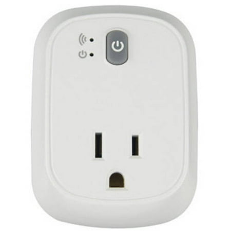
A while ago this blog (http://thegreatgeekery.blogspot.de/2016/02/ecoplug-wifi-switch-hacking.html) was featured on hackaday. I went on the search to buy one to play with. I found them at walmart for a decent price. For those who didn't read the blog at that I mentioned.
 These outlets have an ESP8266 in them which make them great for hacking purposes. The one I got from Walmart actually included the current monitoring circuity if you want to implement power consumption. If you ware going to take the work choice outlet apart be careful when putting it back together. I broke the wires that connect the low voltage board to the high voltage board off of both boards. Just something to be aware of. I also added a programming header to the side so I do not need to take it apart anymore to update the code. I plan on doing over the air updates but I haven't figured that part out yet.


While I did just convert that to my openhab setup, I have also been working on building my own from scratch. Which in the long run is very easy, I only used the following parts
  • ESP8266 development board
  • small bread board
  • 2 channel relay control board
  • 5v power supply
  • 2 buttons
  • outlet
  • box
  • 2 ws2812 leds (optional)
Since I was trying to do this as inexpensively as I could I bought all of the electronics from china. All of the electronics where under $10. I bought the outlet, double gang box and face plate from my local hardware store for under $5. The LEDs are behind the buttons which give them a nice little glow. I am planning on reprinting the orange one soon so it fills the holes a little better and glows more evenly.


The code for both of these projects were almost the same. I had to change the I/O some and the device ID but otherwise the code was the exact same. I did not use the energy monitoring from the commercially available product. One problem i do have currently is when i first plug in the double outlet the one outlet gets turned on for a little bit of time and then it turns right off again. It looks like the pin gets pulled low while the ESP is booting up. I need to go take a look at this and change the output pins so that this problem goes away

Above is the programming board that I made. The header on the left goes to the new header on the side of the workchoice. It has the following pin out not in that order. 
  • 3.3 v
  • gnd
  • reset
  • gpio0
  • tx
  • rx
I also have a header on there if I want to program an esp 1. The right header is for my ftdi cable. Unluckily it has a 5 v power line even though it is 3.3v logic level so I had to put a voltage regulator on there. Another capacitor wouldn't hurt to help smooth out the output since it is an lm3171 but it is working fine for now. . Next is to build a nice looking outlet from scratch, then on to a light switch. But before I get to that I need to find a nice 120 vac to 3.3 vdc circuit as well as prototype with triacs instead. I also want to use capacitive touch instead of actual buttons since I can find a good button for my light switch.


Wednesday, September 9, 2015

Home Automation Part 5 ESP Code


After a lot of time siting frustrated in front of my computer going why doesn't this work and why does that I finally have code that works. A section of the code is still basically the same as with the Ethernet code I had before but I had to go through all of that and change a bunch of variables and references because of how the new library worked. Currently the ESP is set to DHCP because every time I try to set the ip address to 192.168.x.x it claims to have an address of 192.0.0.0 so I am still going to try to to get a static ip setup but the god news is that the router I am using is DDWRT and I think it gives an ip address out based on the mac address so the ESP gets the same ip address each time. I am also able to set a static ip on the router. For my purposes I do not care what the ip address is for each device, what I care about is the devID I give it. My code is in the link below. Most of it I can explain. Some of the stuff in the callback function I am a bit confused on but it works. You can get the topic that was received to come in as a string but the message is not a string or a char so you need to do some funky things to it.

When I was getting everything buttoned up yesterday I was curious how much current was being drawn so I hooked my voltmeter up in series and everything was working fine. I was still modifiying code at this point and after a little while I kept getting stack errors and the serial port would go nuts with information. Then the ESP would reboot and work fine again for a little and repeat. After searching the internet it turns out that it was a power supply issue. Now my volt meter said I was only using about 0.1 amps so I didn't think it was a current draw issue but after a while I took the volt meter out of the loop and it has run since without any issues.

After getting everything working how I wanted it was time to start moving onto the next step. The enclosure. In the long run I want to make a light switch replacement but I figured start with something simple. I happened to have this nice enclosure box and a few outlets so I am going to make a floor switch with 2 buttons ontop that you can push with your feet. This will make it easy to test while I figure out a good small setup for a light switch replacement.


Code

Tuesday, September 1, 2015

Home Automation Part 4 Mosquito v1.4 and ESP start

Now that I have some free time again it is back to work on my home automation stuff. For the past few days I have been working on this and have been slowly figuring out my problems.

  1. Programming. I bought a few esp-07 off of banggood.com for under 4 bucks a pop. While there I also bought a ftdi board so I could program them. The ftdi board works fine as a serial monitor but when it comes to programming it just doesn't work. Not sure what the problem was but I couldn't get it to work. Currently I am using an old USB to xbee board and that is working without a problem. If you are trying to program the ESPs and are having issues try a different ftdi device. 
  2. The Arduino IDE is where I have the most programming experience so I am going to stick with it. I know some people hate arduino with a burning passion but for me its simple (for the most part) and what I have the most experience with. Now in a previous post I talked about how to get an arduino with an Ethernet shield publishing and subscribing to MQTT messages. Once you have added the ESP board to the arduino board it is easy to program them as long as you ave the correct pins grounded or 3.3v See the Schematic below. But the PubSub library I was using before does not work with the ESP. Now I found this library. Now the problem with this is both of the libraries, the one I use with the Ethernet shield and the one I am now using both use pubsub. So the arduino IDE picks the one it thinks it should use which causes problems. I just removed the original one for now and have not tried the new one with the Ethernet shield. 
  3. Mosquito MQTT. With the Ethernet shield and the rpi I had no issues with the mosquito install. Now however with the new library I needed to upgrade mosquito. The code to install the new version is below.  Got the code from http://mosquitto.org/2013/01/mosquitto-debian-repository/
    wget http://repo.mosquitto.org/debian/mosquitto-repo.gpg.key
    sudo apt-key add mosquitto-repo.gpg.key
     cd /etc/apt/sources.list.d/
    sudo wget http://repo.mosquitto.org/debian/mosquitto-wheezy.list
    sudo apt-get update
    sudo apt-get install mosquitto


Wednesday, June 10, 2015

Home Automation Part 3 rpi static ip, On LED, and Arduino Code

Static IP

The worst thing that can happen to you is your ip address on your server changing every once in a while. When that happens you either need to change it back or change all of your devices that talk to it. So you will want to nip that in the but early and set a static ip address for your server that is never going to change. To do that you need to modify /etc/network/interfaces
sudo nano /etc/network/interfaces
In that file you will see either iface eth0 inet dhcp or iface eth0 inet manual. we need to change that to iface eth0 inet static
Now that we are not getting information from the router we need to set that information our selves. Copy and paste below into the file. X should be the "class" of your router. Class is the best name I got. Most routers use either 0 or 1. A should be the address you want your server to be. It has to be between 1 and 254 and cant be your gateway. Pick your poison. B is where you can access the router config. This is usually either 1 or 254
address 192.168.X.A
netmask 255.255.255.0
network 192.168.X.0
broadcast 192.168.X.255
gateway 192.168.X.B
While we at it we might as well change the hostname of the pi. it standard name is I believe raspberrypi. There are 2 files we need to modify. /etc/hosts and /etc/hostname
sudo nano /etc/hosts
You want to change the last line which starts with 127.0.1.1 to whatever you want your hostname to be.
sudo nano /etc/hostname 
Change this file to the same as in the previous file.Then run the following commands to update the hostname and reboot the pi.
sudo /etc/init.d/hostname.sh
sudo reboot
Now make sure when you ssh back into the pi you use your new ip address

On LED

Now I get tired of having to guess when I can ssh back into my pi everytime I reboot it. So I created a small script that turns an LED on when I can ssh back in. 
# export GPIO pin 4 and set to output
echo "4" > /sys/class/gpio/export
echo "out" > /sys/class/gpio/gpio4/direction
echo 1 > /sys/class/gpio/gpio4/value

Basically you set a gpio to output, and set the pin to on or 1. In the above I use pin 4 since it had a ground right next to it. Then wire an LED to it with the proper polarity and run the script at start. To make ir run at start add sudo sh /location/of/script/name.sh  before exit 0
sudo nano /etc/rc.local

Now every time the pi restarts the LED will turn on when you can access it again. It also will turn off when the pi is completely shutdown letting you know when you can unplug it safely.  

Arduino Code

For testing purposes I have been using an arduino UNO with an Ethernet shield. The code so far has not been test on anything but that. What I have done with the code is everything that needs to be changed is changed in the variables at the top of the code. There are only 3 things that need to be changed. 1st is the devID. This is the ip address of the device as well as what topics it subscribes and publishes too. Second is IOcount. This is the number of buttons and outputs you have. For simplicity I have one button for each output. In the code the buttons will turn the output on when they have internet access or don't. The last item that needs to be changed is the mac address. I am planning on making that dependent on the devID as well that way it is one less item that needs to be changed. For outputs I am using the analog pins A0-5 and for inputs I am using 2,3,5-8. I am sure that my code could be improved upon and if you do let me know but here it is as of now. you will need to install the pubsubclient library and make sure it is installed properly, I had to move folders around due to the version number. Arduino Code Download. Now it is time to get the ESP8266-07 working.

Tuesday, June 2, 2015

Home Automation Post 2 openhab and mosquitto install

I have been messing around with openhab for a little bit now and I could not get mqtt to work for the life of me. So what do you do, start back at the beginning. Since this is the beginning of the project the only thing I lost was the rasbian image (which is just a few clicks and some time away from being installed) mosquitto install, and openhab install. This time I followed different installers for openhab and mosquitto and would you know. Now mqtt works without an issue.

OPENHAB
To install openhab I followed the directions on https://github.com/openhab/openhab/wiki/Linux---OS-X. Make sure that if you want to use mqtt you install that addon using _________

echo "deb http://dl.bintray.com/openhab/apt-repo stable main" | sudo tee /etc/apt/sources.list.d/openhab.list #part of previous line
sudo apt-get update
sudo apt-get install openhab-runtime
#will have to type a small y in to install packages
sudo apt-get install openhab-addon-binding-mqtt
#will have to type a small y in to install package
sudo update-rc.d openhab defaults # makes openhab run at boot

MOSQUITTO
mosquitto was a bit easier to install

sudo apt-get install mosquitto mosquitto-clients python-mosquitto


Wednesday, May 20, 2015

Raspberry Pi Picture Frame Post After finished

A useful tool for configuring wifi from the command line is wicd-curses. It gives you an almost gui interface in the command line. Great for configuring wifi over ssh. To insall
sudo apt-get update
sudo apt-get install wicd-curses